发布时间:2024-09-13 06:30:12 人气:
什么是LPR三相逆变器?
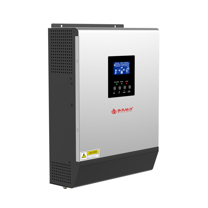
LPR三相逆变器:LPR 是Load Power Regulator(负载功率调节器)的缩写,这是一款可以根据负载(3相)功率来调节输出功率及频率的逆变器,它可以大大减小对额定启动功率的要求(通常逆变器功率的选择是 负载功率的3到4倍)。目前市面上这种逆变器很少。以下是一款比较靠谱的这类逆变器的相关参数。
DC48V96V384V转380VAC三相交流 220VAC 三相交流
LPR三相380V逆变器 LPR三相220V逆变器
一、特点:
●输出频率电压可调
● 完全隔离型逆变技术,纯正弦波输出,不伤害用电设备。
●CPU智能控制管理,逆变单元采用先进的SPWM技术,波形纯净
● 独有的动态电流环控制技术确保逆变器可靠运行
●高转换效率,带载能力及抗冲击能力超强。
●保护功能完善,如过欠压、短路及过载保护等。
●LED+LCD显示,直观显示全部运行参数,状态一目了然。
●高频结构设计,空载小,不受感性负载谐波干扰,更安全更稳定
●适用范围广如:电机,水泵,升降机,伺服器动工具、工业设备、电信设备等各类负载。
二、规格型号
DC48V-AC380V 1KVA~30KVA
DC96V-AC380V 1KVA~50KVA
DC110V-AC380V1KVA~80KVA
DC220V-AC380V1KVA~100KVA
DC336V-AC380V1KVA~100KVA
DC384V-AC380V1KVA~100KVA
逆变输出:AC220V / AC380V 0-60HZ
三、主要技术参数
1KVA-100KVA
直流输入
额定电压:(可选)48VDC/96VDC/110VDC/192VDC/216VDC/336VDC/384VDC/480VDC
电池数量:(可选)4节/8节/9节/16节/18节/32节/18节/28节/32节/40节
电池类型:免维护铅酸蓄电池
逆变输出
额定功率: 1KVA-100KVA
频率: 0-60Hz±1%
波形失真率:≤5%(线性负载)
动态响应:5%(0%~100%负载)
峰值系数(CF): 3:1
功率因数: 0.8
逆变效率:88%
报警: LED指示灯报警和液晶显示屏文字报警
人机界面: LCD液晶
噪音:≤55db
绝缘强度:1500 VAC,1min(输入和输出)
冷却方式:风扇强制风冷
与逆变器相关的英文文章
Inverter may refer to
Inverter (electrical), a device that converts direct current to alternating current
Inverter (air conditioning), an air conditioner that can continuously regulate its output by altering the compressor speed in response to cooling demand
Uninterruptible power supply, which often are based on an electrical inverter
Inverter (logic gate), a logic gate also called a NOT gate
Inverter (electrical)
An inverter is an electrical device that converts direct current (DC) to alternating current (AC); the converted AC can be at any required voltage and frequency with the use of appropriate transformers, switching, and control circuits.
Static inverters have no moving parts and are used in a wide range of applications, from small switching power supplies in computers, to large electric utility high-voltage direct current applications that transport bulk power. Inverters are commonly used to supply AC power from DC sources such as solar panels or batteries.
The electrical inverter is a high-power electronic oscillator. It is so named because early mechanical AC to DC converters were made to work in reverse, and thus were "inverted", to convert DC to AC.
The inverter performs the opposite function of a rectifier.
Applications
DC power source utilization
An inverter converts the DC electricity from sources such as batteries, solar panels, or fuel cells to AC electricity. The electricity can be at any required voltage; in particular it can operate AC equipment designed for mains operation, or rectified to produce DC at any desired voltage.
Grid tie inverters can feed energy back into the distribution network because they produce alternating current with the same wave shape and frequency as supplied by the distribution system. They can also switch off automatically in the event of a blackout.
Micro-inverters convert direct current from individual solar panels into alternating current for the electric grid.
Uninterruptible power supplies
An uninterruptible power supply (UPS) uses batteries and an inverter to supply AC power when main power is not available. When main power is restored, a rectifier is used to supply DC power to recharge the batteries.
Induction heating
Inverters convert low frequency main AC power to a higher frequency for use in induction heating. To do this, AC power is first rectified to provide DC power. The inverter then changes the DC power to high frequency AC power.
[edit] HVDC power transmission
With HVDC power transmission, AC power is rectified and high voltage DC power is transmitted to another location. At the receiving location, an inverter in a static inverter plant converts the power back to AC.
[edit] Variable-frequency drives
Main article: variable-frequency drive
A variable-frequency drive controls the operating speed of an AC motor by controlling the frequency and voltage of the power supplied to the motor. An inverter provides the controlled power. In most cases, the variable-frequency drive includes a rectifier so that DC power for the inverter can be provided from main AC power. Since an inverter is the key component, variable-frequency drives are sometimes called inverter drives or just inverters.
[edit] Electric vehicle drives
Adjustable speed motor control inverters are currently used to power the traction motors in some electric and diesel-electric rail vehicles as well as some battery electric vehicles and hybrid electric highway vehicles such as the Toyota Prius. Various improvements in inverter technology are being developed specifically for electric vehicle applications.[2] In vehicles with regenerative braking, the inverter also takes power from the motor (now acting as a generator) and stores it in the batteries.
[edit] Air conditioning
Main article: Inverter (air conditioning)
An air conditioner bearing the inverter tag uses a variable-frequency drive to control the speed of the motor and thus the compressor.
[edit] The general case
A transformer allows AC power to be converted to any desired voltage, but at the same frequency. Inverters, plus rectifiers for DC, can be designed to convert from any voltage, AC or DC, to any other voltage, also AC or DC, at any desired frequency. The output power can never exceed the input power, but efficiencies can be high, with a small proportion of the power dissipated as waste heat.
Warnings
Some low power inverters have a warning not to use conventional fluorescent lighting. This is due to the power correction capacitor connected in parallel with the lamp. Removing the capacitor will fix the problem. What may not be known is that in dual lamp fittings the capacitor may be connected in series with the second lamp, thus removing the problem as well as the stroboscopic effect caused by the mains frequency.
Basic designs
In one simple inverter circuit, DC power is connected to a transformer through the centre tap of the primary winding. A switch is rapidly switched back and forth to allow current to flow back to the DC source following two alternate paths through one end of the primary winding and then the other. The alternation of the direction of current in the primary winding of the transformer produces alternating current (AC) in the secondary circuit.
The electromechanical version of the switching device includes two stationary contacts and a spring supported moving contact. The spring holds the movable contact against one of the stationary contacts and an electromagnet pulls the movable contact to the opposite stationary contact. The current in the electromagnet is interrupted by the action of the switch so that the switch continually switches rapidly back and forth. This type of electromechanical inverter switch, called a vibrator or buzzer, was once used in vacuum tube automobile radios. A similar mechanism has been used in door bells, buzzers and tattoo guns.
As they became available with adequate power ratings, transistors and various other types of semiconductor switches have been incorporated into inverter circuit designs.
[edit] Output waveforms
The switch in the simple inverter described above, when not coupled to an output transformer, produces a square voltage waveform due to its simple off and on nature as opposed to the sinusoidal waveform that is the usual waveform of an AC power supply. Using Fourier analysis, periodic waveforms are represented as the sum of an infinite series of sine waves. The sine wave that has the same frequency as the original waveform is called the fundamental component. The other sine waves, called harmonics, that are included in the series have frequencies that are integral multiples of the fundamental frequency.
The quality of the inverter output waveform can be expressed by using the Fourier analysis data to calculate the total harmonic distortion (THD). The total harmonic distortion is the square root of the sum of the squares of the harmonic voltages divided by the fundamental voltage:
The quality of output waveform that is needed from an inverter depends on the characteristics of the connected load. Some loads need a nearly perfect sine wave voltage supply in order to work properly. Other loads may work quite well with a square wave voltage.
[edit] Advanced designs
H-bridge inverter circuit with transistor switches and antiparallel diodesThere are many different power circuit topologies and control strategies used in inverter designs. Different design approaches address various issues that may be more or less important depending on the way that the inverter is intended to be used.
The issue of waveform quality can be addressed in many ways. Capacitors and inductors can be used to filter the waveform. If the design includes a transformer, filtering can be applied to the primary or the secondary side of the transformer or to both sides. Low-pass filters are applied to allow the fundamental component of the waveform to pass to the output while limiting the passage of the harmonic components. If the inverter is designed to provide power at a fixed frequency, a resonant filter can be used. For an adjustable frequency inverter, the filter must be tuned to a frequency that is above the maximum fundamental frequency.
Since most loads contain inductance, feedback rectifiers or antiparallel diodes are often connected across each semiconductor switch to provide a path for the peak inductive load current when the switch is turned off. The antiparallel diodes are somewhat similar to the freewheeling diodes used in AC/DC converter circuits.
Fourier analysis reveals that a waveform, like a square wave, that is antisymmetrical about the 180 degree point contains only odd harmonics, the 3rd, 5th, 7th etc. Waveforms that have steps of certain widths and heights eliminate or “cancel” additional harmonics. For example, by inserting a zero-voltage step between the positive and negative sections of the square-wave, all of the harmonics that are divisible by three can be eliminated. That leaves only the 5th, 7th, 11th, 13th etc. The required width of the steps is one third of the period for each of the positive and negative steps and one sixth of the period for each of the zero-voltage steps.
Changing the square wave as described above is an example of pulse-width modulation (PWM). Modulating, or regulating the width of a square-wave pulse is often used as a method of regulating or adjusting an inverter's output voltage. When voltage control is not required, a fixed pulse width can be selected to reduce or eliminate selected harmonics. Harmonic elimination techniques are generally applied to the lowest harmonics because filtering is more effective at high frequencies than at low frequencies. Multiple pulse-width or carrier based PWM control schemes produce waveforms that are composed of many narrow pulses. The frequency represented by the number of narrow pulses per second is called the switching frequency or carrier frequency. These control schemes are often used in variable-frequency motor control inverters because they allow a wide range of output voltage and frequency adjustment while also improving the quality of the waveform.
Multilevel inverters provide another approach to harmonic cancellation. Multilevel inverters provide an output waveform that exhibits multiple steps at several voltage levels. For example, it is possible to produce a more sinusoidal wave by having split-rail direct current inputs at two voltages, or positive and negative inputs with a central ground. By connecting the inverter output terminals in sequence between the positive rail and ground, the positive rail and the negative rail, the ground rail and the negative rail, then both to the ground rail, a stepped waveform is generated at the inverter output. This is an example of a three level inverter: the two voltages and ground.[3]
[edit] Three phase inverters
3-phase inverter with wye connected loadThree-phase inverters are used for variable-frequency drive applications and for high power applications such as HVDC power transmission. A basic three-phase inverter consists of three single-phase inverter switches each connected to one of the three load terminals. For the most basic control scheme, the operation of the three switches is coordinated so that one switch operates at each 60 degree point of the fundamental output waveform. This creates a line-to-line output waveform that has six steps. The six-step waveform has a zero-voltage step between the positive and negative sections of the square-wave such that the harmonics that are multiples of three are eliminated as described above. When carrier-based PWM techniques are applied to six-step waveforms, the basic overall shape, or envelope, of the waveform is retained so that the 3rd harmonic and its multiples are cancelled.
3-phase inverter switching circuit showing 6-step switching sequence and waveform of voltage between terminals A and CTo construct inverters with higher power ratings, two six-step three-phase inverters can be connected in parallel for a higher current rating or in series for a higher voltage rating. In either case, the output waveforms are phase shifted to obtain a 12-step waveform. If additional inverters are combined, an 18-step inverter is obtained with three inverters etc. Although inverters are usually combined for the purpose of achieving increased voltage or current ratings, the quality of the waveform is improved as well.
UPS电源status:bypass output
这种显示是工作在旁路状态,正常是工作在逆变器状态的类似“load on inverter"
可能原因有几个:
逆变器(INVERTER)故障
逆变器(INVERTER)温度过高
过载
主电源没电,电池放电截止后转旁路
人为转旁路
关机后没开机即逆变器(INVERTER),按类似“逆变器启动”“UPS ON”键启动
你说“但是这个UPS好像过个一段时间,嘟的响一下,感觉好恐怖啊,很短的一下,在、不知道是什么原因?现在面板无显示了”
检查:
1.输入有无正常电源
2.电池是否过放造成内部电源关闭无显示
不知道你的UPS什么品牌型号等,所以只能到这里了 ,感觉你的设备可能坏了
chk009电路原理
000 POWER ON:驱动器供电正常。
001 NEW RUN:重新初始化运行。
002 GO TO SLEEP: 变频器进入节能模式。
003 STACK WARN: 软件中堆找超出允许范围。
004 POWER DOWN:记录一个断点信号,即拉闸。
005 EXTERN FLASH: GDCB的FLASH内存记录失败。
006 EXTERN RAM: GDCB的RAM内存记录失败。
007 OMU PRESENT: 表明OMU已插在变频器的相应接口上可以正常使用。
008 OMU PROHIBIT: 检修模式下OMU的软件升级被禁止, TT参数OMU PROHIBITED来 查看。
009 MANUAL MODE: 变频器在手动模式下。
010 B_MODE: 变频器在电池模式下。
011 EXTERN FRAM: FRAM通讯正常。
100 INV SW OCT: 变频器电流大小超出了允许的上限。
101 INV I IMBAL:电机三相总电流超出满载电流的10%。
102 INV ID ERROR,103 INV IQ ERROR: 表明变频器电流校准误差超出允许的上限。
104 INV IX OFFST,105 INV IY OFFST,106 INV IZ OFFST:表明变频器相电流偏移量超出满载时的5%。
107 INV GATE FLT: 检测到IGBT门电路供电电压故障。
108 INV HW OCT: 硬件检测到变频器电流超出了预设值。
109 OVERLOAD: 检测到过载。变频器处于额定电流状态的时间超出了最大允许值。
110 DRIVE LIMIT: 变频器已运行在额定电流的极限值。
111 NO ID FDBK,112 NO IQ FDBK: 在电机开始运行并产生磁场时通过变频器的电路反馈已检测到一个故障。
113 INV IPM FIT: 变频器智能电源模块已检测到一个故障。
114 GATESPIYERR: 检测到变频器和逆频器IGBT门电路电压故障。
115 DESAT ERR: 硬件检测到变频器电流超出预设值。
200 CNV SW OCT: 逆变器电流大小超出了允许的上限。
201 CNV ID ERROR,202 CNV IQ ERROR: 表明逆变器电流误差超出满载时的30%。
203 CNV IX OFFST,204 CNV IY OFFST: 表明逆变器相电流的偏差超出满载时的5%。
205 CNV GATE FIT:检测到逆变器IGBT门电路供电电压故障。
206 CNV HW OCT: 检测到逆变器电流超出预设值。
207 CNV GND FLT: 检测到逆变器有接地故障。
208 BUS CAP FAIL: 变频器的功率损耗超出了预估值的极限。这表明过多的功率损耗在变频器内,同时也是暗示直流侧电容可能已失效。
209 DC LINK OCT:表明直流电流过大
210 CNV IPM FLT: 逆变器智能电源模块已检测到一个故障。
300 DC BUS OVER: 直流电压超出750V的108%,即810V。
301 DC BUS UNDER:直流电压低于下极限值。
302 VAC OVER: 交流电压超出上极限值。
303 VAC UNDER: 交流电压低于下极限值。
304 VAC IMBAL: 交流相电压输入相差超过10%.
305 PLL UNLOCK: 处于相锁定循环的交流相电压已解锁,通常发生在你试图运行一个IGBT已损坏的变频器。
306 SINGLE PHASE: 表明变频器处于单相模式并且T相接在一稳定的输入电压上。单相供电仅使用T相供电,其他相不接。
307 PLL FREQ RNG: 当没有PLL UNLOCK故障且变频器交流线电压频率超出44《F《66HZ时记录此故障,这也暗示交流线电压存在故障。
308 WELDED MXPX: 当变频器的供电进入逐渐下降状态时,如果直流电压在15秒内不下降到底于某一电压下限时,系统将显示MX或PX接触器未动作。
309 VSCALES OFF: 当测量到的交流线电压和直流电压明显不匹配时记录此故障。此检测只在电梯处于IDLE状态两电压有足够时间处于稳定值时测量。
310 AC BROWN-OUT: 此故障只是表示交流线电压压降已超过预先设定值的15%,当交流线电压压降低于预先设定值的30%时记录“303 VAC UNDE”故障。变频器将降级运行 并降低运行曲线。但是一旦出现“303 VAC UNDE”故障变频器将结束当前运行后死机。
400 BRAKE S1,401 BRAKE S2: 此故障表明抱闸开关的状态有错误。请分别在电梯运行中和停止后检查抱闸开关的状态。
402 BRAKE STATUS: 从抱闸模块反馈的抱闸状态不正确。
403 BRAKE BY: 一个或两个BY继电器的常闭触点吸合状态不正确。在给抱闸的命令发出前,且电梯将要运行时BY继电器应吸合。
404 BK DESAT ERR: 硬件检测到抱闸电流超出预设值。
405 BK BUS OVER: 抱闸供电直流电压超出上限值。
406 BK BUS UNDER: 抱闸供电直流电压超出下限值。
407 BK FBK TMOUT: 抱闸反馈超时。
408 BK SW OCT: 抱闸电流的大小超出了允许的极限值。
500 OVERSPEED: 电机运行超速,速度上限是根据变频器操作模式有所不同。
501 POS TRACKING: 位置跟踪误差超出极限值,同时表明位置反馈和运行曲线电梯应处的位置不一致。 502 VEL TRACKING: 速度跟踪误差超出了极限值。速度反馈和跟踪到的速度曲线不一致。
503 LRT MOTION: 此故障表明在进行转子锁定测试时检测到转子有转动。当使用的电机是PM电机时,转子锁定测试是在上电确定磁铁位置后首次运行时最先做的工作。该上限是1电弧度位移,如果发生此类故障,则可能是抱闸没有调整好。
504 ENC POS ERR: 在电机为PM电机时,此故障表明驱动对磁场位置的跟踪丢失。此故障对减少扭矩损失是必要的,它可能由于电机偏码器有机械滑移引起,或者在锁定转子测 试时磁铁位置计算错误引起。
505 TRACTION ERR: 未使用。
506 STOPPING ERR: 没有在规定的时间内找到桥板。
507 POS AT 1LS: 1LS位置不合适。电梯不在1LS范围内时1LS信号大小写状态发生转变或1LS信号大写时与电梯所处的井道位置不一致。
508 POS AT 2LS:2LS位置不合适。电梯不在2LS范围内时2LS信号大小写状态发生转变或2LS信号大写时与电梯所处的井道位置不一致。
509 FLOOR AT 1LS: 当1LS有效时电梯所处楼层不正确。1LS的大小写转换发生在1LS范围外的楼层。
510 FLOOR AT 2LS: 当2LS有效时电梯所处楼层不正确。2LS的大小写转换发生在2LS范围外的楼层。
511 1LS & 2LS : 两个LS信号同时有效,即1LS和2LS同时变大写了。
512 MISSING VANE: 电梯经过一个桥板时平层信号没有大小写转换。在检修或校正运行时不检测。
513 NO PRS TRANS: 当电梯在一个平层位置时,即位置传感器处于桥板中时平层的大小写信号没有转换。在检修或校正运行时不检测。
514 ENC <>VANE: 有一个不正确的平层信号被检测到。
515 NTSD FAILED: 在正常运行中,正常的停止曲线不能使电梯减速恰好停止在目标楼层。减速时间分成两段,包括一段爬行时间仅用于在端站缓速之用。记录此故障的条件是用 正常运行时错过目标楼层时的速度与正常减速度110%减速曲线运行的速度比较,高于此值则记录此故障。
516 CORR FAILED: 校正运行丢失位置。当校正运行至端站时超出极限开关或超出桥板,或者根本就不处于预计的端站位置时记录此故障。当电梯停梯时记录此故障。
517 DDP ERROR:延迟驱动保护故障。经过两个桥板之间的时间超出了设定值。在自学习或检修运行期间不检测。此故障仅在电源倒换或软件复位时清除,通过设定参数DDP SEC来决定时间。
518 BELTCMP ERR: 在自学习期间关于补偿链和随缆的不平衡的补偿系数有错误。这个补偿系数既不能是复值也不能过大(它的变化范围应该是使电梯在顶层运行与在底层运行的 电机扭矩相差不超过30%)此补偿系数可以查看以下参数:BELTCMP:SLP MA/M,BELTCMP:OFFSET A.
519 RLVPERMITERR: 在称量系统处于重载情况下控制系统允许再平层,但此状态持续的时间已超过200ms。
520 RLLBCK START: 在启动运行时反拉车超过5mm。
521 RLLBCK STOP: 在停车时未达到或超出桥板超过5mm
522 MANUALRESCUE: 通告SPBC已手动救援运行电梯(电梯断电,由SPBC打开抱闸)。变频器里储存的电梯位置信息作废且下次电梯运行前会重新做锁定转子测试。
523 MOVED AT POF: SPBC和变频器位置信息矛盾(上电时):变频器会以SPBC的位置为准。
524 NO ENC SIGNL: 偏码器A信号频道没有检测到。偏码器可能未接好,偏码器供电不正常或编码器已损坏。
525 NORLV SPDCHK: 再平层速度过高(>=0.285m/s)
526 NORLV TOOMNY: 连续尝试了20次再平层运行电梯还是不能处于可正常运行的位置。
527 NORLV LOSTDZ: 丢失DZ信号或检测到UIS/DIS信号门区位置不正确(与平层桥板有几毫米误差导致不能识别平层信号)
528 PROFILE ERR: 1LS或2LS长度过短(自学习期间)导致电梯不能找到正确位置。此故障可能由于设置的速度曲线速度过大或者开始时加速度过小。另外还可能是LS的磁条 确实过短。
529 NO ENC FDBCK: 此故障表明电梯有移动但编码器没有反应。当编码器反馈速度低于1mm/s时如果电机电压超过参数NO ENC VTHRS PU值时记录此故障。
530 NO ENC TMOUT: 此故障表明电梯已运行速度曲线而电机的速度反馈在参数 NO ENC FLT TSEC规定的时间内没有超过1MM/s.
531 PRS SINGS 1LS: 1Ls的大小写变化位置与自学时测定的1LS大小写转换点位置不一致。
532 PRS SINGS 2LS: 2LS的大小写变化位置与自学时测定的2LS大小写转换点位置不一致。
533 ARO OVERSPD: 此故障表明电机速度超过参数ARO OVERSPEED%值。当ARO OVERSPEED%=0时,取消此功能。一旦记录此故障,电梯会发生急停。
600 INV TMP WARN: 变频器的散热温度已超过80度。
601 INV TMP OVER: 变频器的散热温度已超过85度。此故障的检测有一定的滞后性,除非温度已低于退出热保温度5度才能退出热保状态。
602 INV TMP FAIL: 表明在变频器中的热感元件没有连接或已经失败。此时风扇将启动并且直到此故障消除才能停止风扇转动。
603 CNV TMP WARN: 逆变器的温度已经超过80度。
604 CNV TMP OVER: 逆变器的散热温度已超过85度。此故障的检测有一定的滞后性,除非温度已低于退出热保温度5度才能退出热保状态。
605 CNV TMP FAIL: 表明在逆变器中的热感元件没有连接或已经失败。此时风扇将启动并且直到此故障消除才能停止风扇转动。
606 MTR TMP OVER: 电机温感触点已经改变状态,它表明既有可能是电机温度过高也可能是触点电路有问题,需要检查电机温感触点。尽管电机温感触点可以设为常开或常闭,我们通常选用常闭触点。如果需要温感是常开触点,需要对驱动电路进行相应的修改。
607 REACTOR TEMP: 线圈中的温感开关断开表明线圈中出现温度过高的现象。
700 SAFETY CHAIN: 安全链问题,安全链断开会导致SX继电器释放,引起电机和抱闸断电,最终导致急停。
701 NO MAN INPUT: 此故障仅发出在手动模式或手动模式下跳线已取消时。
702 PRECHRG TIME: 此故障表明在正常运行中M1的直流吸合电压不够。它一般在初始化几秒后产生。除非再接到MCSS发出的 准备运行命令否则驱动不再试图预先上电。电压 上限为当前交流线电压平方倍的75%。
703 S RLY FAULT: 常开点S1处于错误的位置。
704 DBD FAULT: S1,S2,BY1,BY2中的一个或更多的常闭点处于错误的位置,在变频器锁定前允许有三次机会去获得正确的信号。
705 E2 INVALID: EEPROM中的数据值与当前SCN或新的EEPROM参数不匹配,无效的值或空着的值必须重新设置。
706 E2 WRITE LIM:允许写入的数据超出了EEPROM的最大值。
707 ADC OFFSET: ADC的偏移量超过ADC总量的2.9%,或ADC增益偏差大于6.5%。相关电路有可能存在问题。
708 CMD TO ABORT: 通过OPB命令终止一次运行,每次检修恢复也会记录。
709 PRS SIGNOISE: 在某一段时间内位置传感器的大小写信号转换过于频繁。
710 UIB DIB ERR: TCBC型控制柜的运行控制信号中没有UIB,DIB信号.
711 DBD SHUTDOWN: S1,S2,BY1,BY2中的一个或更多的常闭点处于错误的位置,在变频器锁定前允许有三次机会去获得正确的信号。
712 POST TRQ TIME: 当电流在规定时间内没有减少到0则记录此故障。
713 BIOCK BY 000: 完成最后一次运行后电梯进入死机状态,故障等级为S的故障可以引起死机,或者某一种故障发生次数超过允许次数会发生死机。可根据手册4.15.2排除故障。
714 B_MODE ERR: 当驱动为TANDEM时不适用电池模式错误。
715 FRAM INVALID: 当GDCB被初化后,不能从FRAM中读取数据。 716 SER FLT: 在第二个变频器中有驱动故障,检查第二个变频器的故障记录。
717 SCR SAS: 在第二个变频器中有SAS故障,检查第二个变频器的故障记录。
800 IMS TASK: 当有通讯正常且同步故障时第二个驱动会检测到此类故障。
801 10ms TASK: 当有通讯正常且同步故障时第二个驱动会检测到此类故障。
802 40MS TASK: 当有通讯正常且同步故障时第二个驱动会检测到此类故障。
803 CNV TASK: 当有通讯正常且同步故障时第二个驱动会检测到此类故障。
804 INV TASK: 当有通讯正常且同步故障时第二个驱动会检测到此类故障。
900 MCSS TIMEOUT: 80毫秒内没有收到MCSS的通讯。
901 SVC TOOL ERR: TT接口通讯错误。
902 CAN ERR: CAN通讯错误被检测到。
903 E2 COMM WRITE: 在向EEPROM写数据时发生错误。
904 LWSS TIMEOUT: 变频器没有在规定的时间内收到负载信息。当检测到LW信息后此故障才能清除。
905 LWSS BAD VAL: 变频器接受的负载信息数值不正确。当检测到LW信息后此故障才能清除。
906 NO LS MSG: 变频器三秒内没有收到LS信号。
907 PRIMARY CRC: 变频器要求执行一个主负载的校验运行,且所得值与等效计算的值不一致。
908 DRIVE CRC: 变频器要求执行一个驱动软件的校验运行,且所得值与等效计算的值不一致。
909 CAN BUSOFF: 变频器的CAN控制器由于CAN总线或CAN电源造成通讯问题且已经死机。
910 CAN OPB-INIT: 初始化CAN通讯软件失败。
911 CAN TXQ FULL: CAN接口的传输数据溢出,传输信息已丢失。
912 SPBC TIMEOUT: SPBC响应变频器的位置请求超时(超时为200ms)
913 MCSS WARNING: 检测到MCSS通讯错误。
914 SEC LNIT ERR: 在初始化完成后主驱动和第二驱动只能进行不超过10秒的SPI通讯,当SPI通讯数据没有更新或错误数据被写入FRAM中,SPI可以保持通讯10秒,可能引起此故障的原因是硬件损坏或设置的参数不正确。如果参数没有完全设好,SPI通讯就不会开始工作,当故障排除后,此故障就自动消除。
915 SYNCH ERR: 在通讯建立后3秒内没有接到SPI通讯的同步信号,可能由于主驱动重启了,也有可能是抱闸的光学模块损坏或光缆断线了。也有可能是SPI通讯板损坏。当故障排除后,此故障就自动消除。
916 PRISEE TMOUT: 在通讯建立后,发生了一个校验错误或计数错误。有可能是主驱动或第二驱动重启。还有可能是FRAM有错误。也有可能是抱闸的光学模块损坏或光缆断线了。也有可能是SPI通讯板损坏。当故障排除后,此故障就自动消除。
车载逆变器哪种比较好~~
英文技术参数Model
Item SM150-212/224 SM300-212/224 SM500-212/224 SM750-212/224
ACOutputVoltage 100/110/120VAC±3%/220VAC±3%
DCinputRange 11V-16VDC/21V-31VDC
MaxTransferEfficiency 90%
ContinueOutputPower 120W 240W 500W 600W
PowerDisplay Display Low40W
nodisplay Low120W
nodisplay Low150W
nodisplay
ShortTimeOutputPower 150W/15min 300W/15min 500W/15min 750W/5min
OutputWave ModifySineWave
Frequency 50Hz
NoLoadDraw 0.4A 0.4A 0.9A 0.9A
LowVoltageShut 10.5V/21VDC
HighVoltageShut 15.8V/31.6VDC
AutoResume NO
UseTemperature 0~60℃
StoreTemperature -20~60℃
FanStart-up NO 40W 120W 150W
Protection Overload、OverVoltage、LowVoltage、Overtemperature
Dimension(mm) 135×85×45 185×85×50 225×105×50 225×105×50
Weight(Kg) 0.5 0.6 1.0 1.0
湖北仙童科技有限公司 高端电力电源全面方案供应商 江生 13997866467